Just a day before I left to Indonesia for my brother’s wedding, I got worried about my headless Linux PC server: it may freeze when I left it. It happened before because of kernel panic and hardware error, it can happen again. I want to be able to reset the PC in case of errors and to power it down in case the error was not recoverable (for example last year my disk drive went bad).
Just a note before reading this: in case you just want to turn on or off a PC using raspberry PI: just use wake on LAN (WOL) to turn on your PC and SSH access to turn it off. Wake on LAN works most of the time, but it can not handle a PC that is not responding.
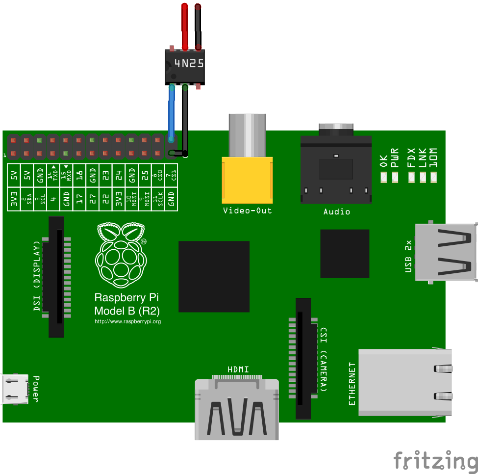
I soldered 2 optocouplers that I have (4N25) to a small perfboard with a pin header. Then I use solderless breadboard cables to connect the board to Raspberry Pi, and to the PC power and reset button (so I can manually turn on/off using the power/reset button on the PC).
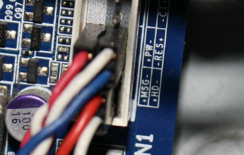
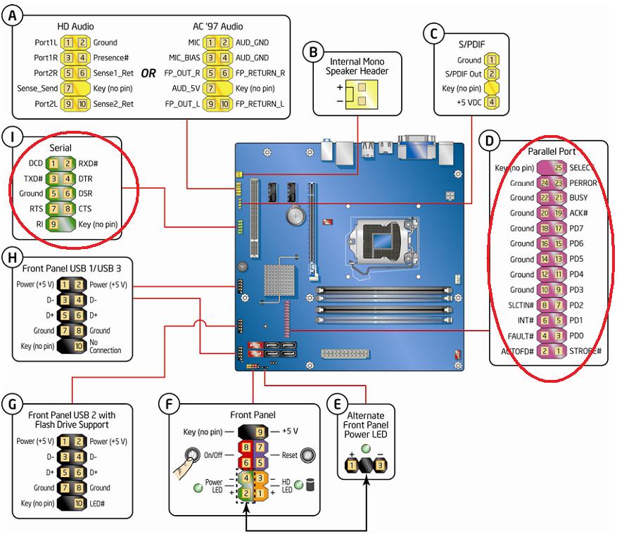
Watch carefully about the + and – on the motherboard (PW is for power, and RES is for reset, note the polarity is important for the optocoupler, on the picture above: Red goes to + and Black goes to -):
I could just have used one optocoupler to connect to the power button (the reset is not really necessary, because we can turn off and on the PC again to reset), but I just want to use the extra 4N25 that I have (it’s really cheap, 5.5 baht or around 17 cents USD).
To reset the PC, I just set the GPIO pin to high for about one second, then set it low again. To power up the PC, I set the GPIO pin to high for about 5 seconds, and set it low again (the same can be used to forcefully power down the PC).
Resetting and powering the PC is easy, the next task is to know what happened if the PC crashed. To do this, I need a serial connection. If my PC has a serial port and I have a USB to serial cable, then everything will be much easier, but since I don’t have a USB to serial cable, and my PC doesn’t have a serial port on the back, it gets a bit complicated.
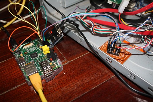
I still have a small board based on MAX3232CPE to convert from 3.3V serial to 5.0 V, so I plugged that board to Raspberry Pi and connected it directly to the PC motherboard. This page helped me in finding the pin names (I only need to connect RX, TX and GND).
On the Raspberry side, I need to set up so that it will not use the serial port for kernel output and log in. You can follow the guide here.
On the PC side, I need to activate serial output in three places: to accept login (getty), to get the kernel output (kernel parameters in grub), and in grub itself (to show the boot selection dialog). This guide for Debian works for me, but I was not able to see the GRUB output on screen when I connected my screen (I can only see the output on my serial console, but this was not a problem for me).

I experimented a little bit with SGABios Hoping that I would be able to see BIOS output from my serial port. It didn’t work as expected. I can not see the initial BIOS screen, and I can not send a key to enter BIOS setting, but If I connect a keyboard and press a button to enter the BIOS, I can see the BIOS menu via serial port and I can interact with it.
Here are the steps that I tried to get the BIOS serial output: I downloaded the BIOS for my motherboard (an AWARD BIOS). Then on a windows machine, I modified the BIOS using CBROM cbrom bios.bin /isa sgabios.bin. Then I flashed the BIOS from Linux using Flashrom.
I didn’t solve the BIOS problem due to time constraint. There are several solutions that I can think of to solve this: one is to use CoreBoot (but unfortunately my motherboard is not supported by coreboot), another one is to try to do more hacking on the BIOS (maybe removing the VGA ROM to force the output to serial port) and the other one is to simulate a keypress to enter BIOS. The first two methods may not be portable across BIOS, but the last one should be portable. The key simulation can be done by simulating a PS2 device (using bitbanging on Raspberry Pi), or USB HID device. A super simple USB HID device can be made by using V-USB library (you can see this as an example).
Just a few hours before I left, I have an idea to connect a temperature sensor just to see if the temperature around the PC case is too high. We are entering the summer here in Chiang Mai and the outside temperature is getting higher every day (from November to beginning of February, the temperature was around 8-20 Celcius, and now it is around 17-37 Celcius). It was quite easy to add the temperature sensor, I just use the guide and driver from adafruit. Next time I may add an infrared LED on the Raspberry Pi to turn on the Air Conditioner when it gets really hot.
Having everything setup: nothing happened while I was away. The PC was running nicely (and I can access the PC via SSH and the serial console).