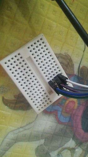
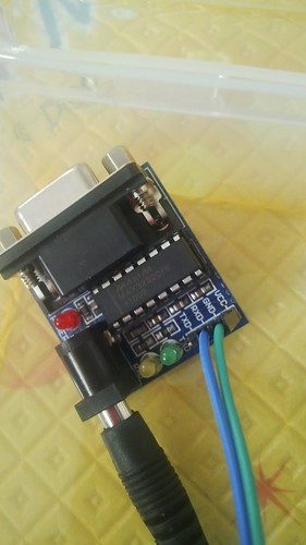
Raspberry Pi as Alphasmart Dana Access Point and File Share

Alphasmart Dana is a Palm OS device with a keyboard form factor that is still popular among writers. One of the Alphasmart Dana version has a wireless capability, but it only supports WEP 40/128 bit. WEP  has a very weak security and is not supposed to be used anymore. Alphasmart Dana also supports SAMBA file share but it only supports SMB1 (which is also considered insecure). Since Alphasmart Dana was made on 2002 and the last software update was 2005, there is no hope for WPA upgrade or newer SMB protocol.

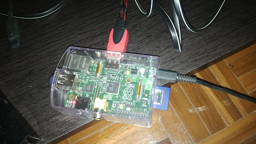
To be able to easily transfer files from/to Alphasmart Dana, I made a special WEP access point with my Raspberry Pi 2 that works on a separate subnet.  I use a cheap RT5370 USB WIFI for the access point and ethernet cable to connect to my local network. In my opinion, this will not be 100% secure but It is enough for my need. It is much better than changing your home WIFI encryption to WEP (which will make everything insecure).

The dongle that I use is very small and the range is only a few meters away, this already helps with security since it will not be accessible outside my house (but a very determined person with the right equipment may still be able to communicate with it). I gave Alphasmart Dana a separate subnet  (172.17.x.x) different from my local network (192.168.x.x) and I did not set it up to forward connections between this two subnets (by default it won’t).

For the file share, I set up one Samba public share to transfer files from/to my Dana. This share is only accessible through the subnet obtained from WEP access point. In the very worst case, if someone can get in, they can steal my files in that share. But since I am not working on anything secret (mostly just my draft for my blog posts), I am willing to accept the risk.

I gave this long explanation about security in case someone wants to make a portable set up out of this guide. If you bring your access point to a coffee shop, someone can break the encryption in a very short time and steal your next best-selling novel. I repeat that my setup is only for my desktop which is only reachable from my bedroom (and I live in a house which is quite far from my neighbors), and I don’t work on important documents.

Access Point

First, we need to setup the static IP address for the wlan0, I choose 172.17.1.1. To do this, create /etc/network/interfaces/wlan0.

auto wlan0
iface wlan0 inet static
    address 172.17.1.1

Then we need to setup DHCP server that will hand out IPs automatically. If you need more security, you can also setup static IP with secret IP address (this is just another layer of obfuscation). I have several Dana in my house (my Wife’s and Children’s).  For DHCP server, I use dnsmasq because it is very simple. Install dnsmasq:

sudo apt-get install  -y dnsmasq

This is what you need to add in /etc/dnsmasq.conf:

dhcp-range=172.17.1.10,172.17.1.250,12h

For the access point part, I use hostapd.  Create /etc/hostapd/hostapd.conf with the following content. The encryption can be 40 bits (5 characters) or 128 bits (16 characters).

interface=wlan0
ssid=dana
hw_mode=g
channel=6
macaddr_acl=0
auth_algs=3
wep_default_key=0
wep_key0="AAAAA"
driver=nl80211

And also set the path to the config in: /etc/default/hostapd

DAEMON_CONF="/etc/hostapd/hostapd.conf"

We also need to disable wpa_supplicant (you may need to restart or kill the wpa_supplicant process if it was already started):

sudo systemctl mask wpa_supplicant.service

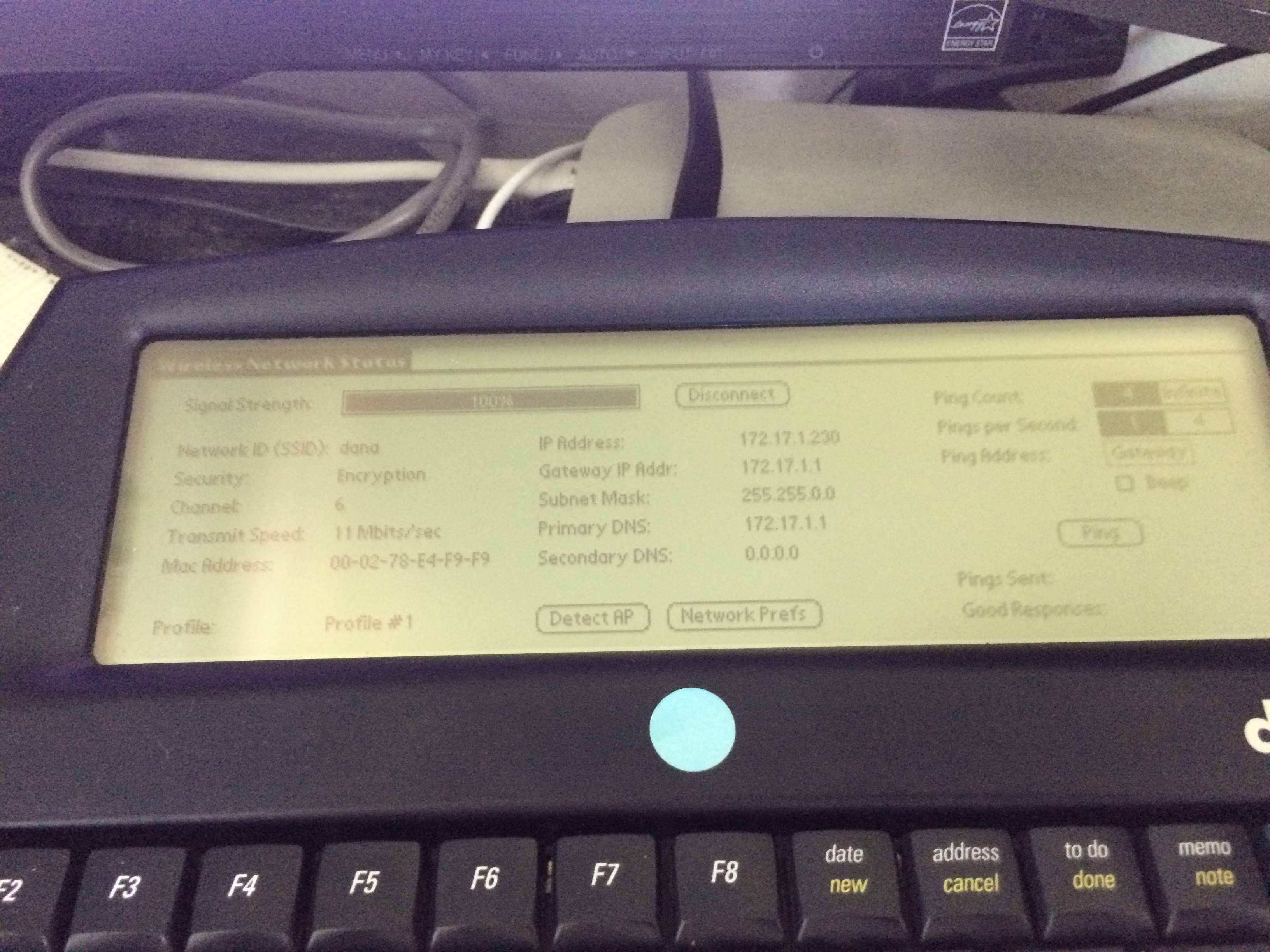
Now we can test this configuration by trying to connect using WiStat from Dana. If you can connect, the first part is complete. But you can’t access any file yet.
File Share

To set up file share, install samba:

sudo apt-get install samba

Edit /etc/samba/smb.conf

inside the “[global]” section add:

[global]
lanman auth = Yes
client lanman auth = Yes
client plaintext auth = Yes
server min protocol = NT1

And to set up a public directory which will be readable/writable by everyone (the name of this share is “dana”, change it as you like):

[dana]
path = /dana
writeable = yes
browseable = yes
public = yes
guest ok = yes
read list = "nobody","@allaccount",
write list = "nobody","@allaccount"

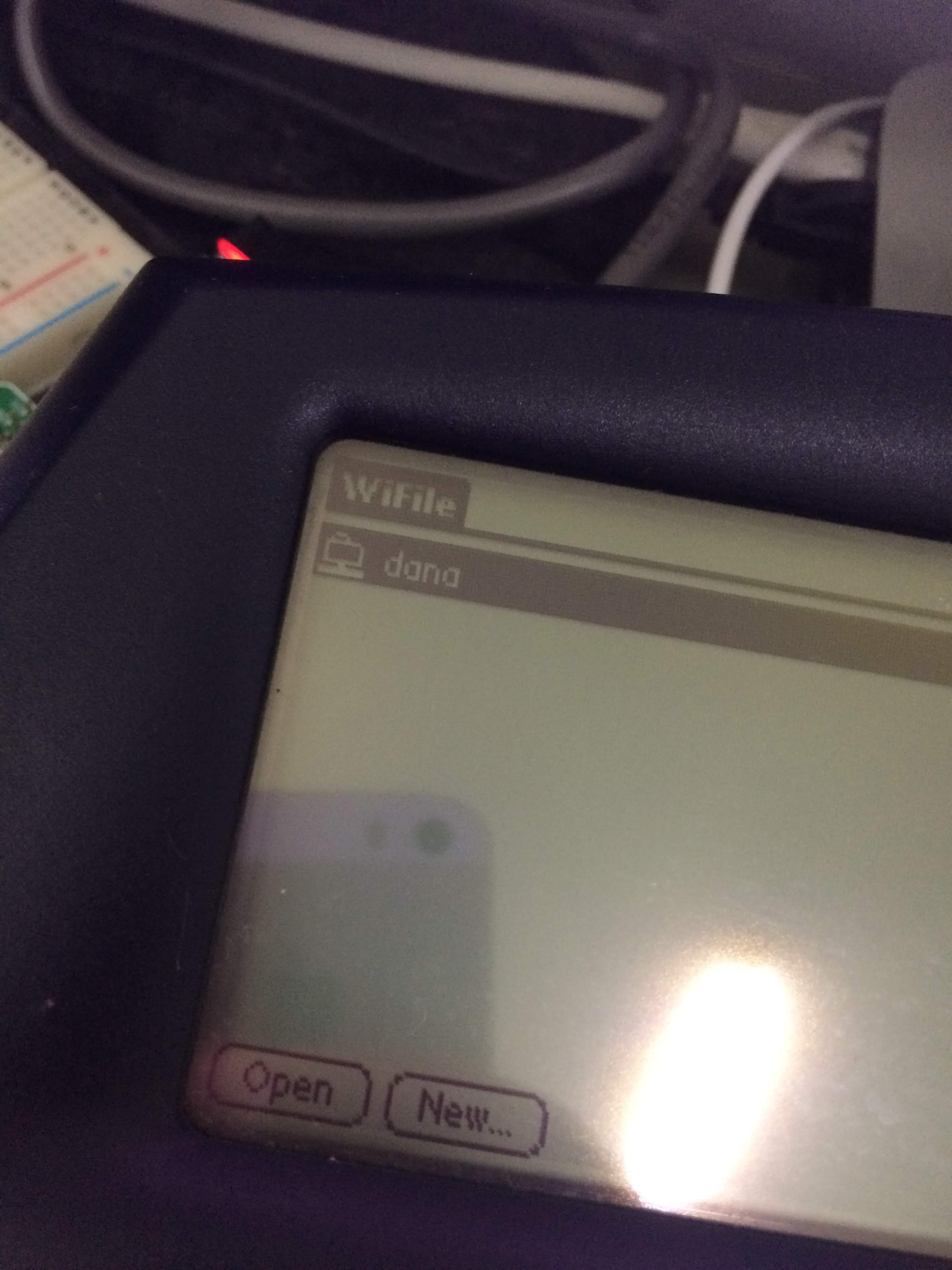
Now you should be able to save/load file from Alphaword to the share, or view the share using WiFile.
DropBox

I will not write a specific instruction for this, you can read this guide on Raspberry Pi website on how to upload your files to Dropbox. I use a cron script that will upload the content of *.txt files to Dropbox. Note that the 172.17.x.x subnet cannot access the internet, but the wired network 192.168.x.x can access the Internet.

So my current workflow is this: I write something on my Dana, and when I reach home, I save the file to the share. In a few minutes, the files are uploaded to Dropbox. Dropbox has a file history feature which is quite useful. Of course, you don’t have to use Dropbox, you can use also use git to have a remote backup with file history.

One step that I wish I could do is: send all my work with a single click. For now, I need to send one file at a time. I hope this guide will be useful to anyone still using Dana (wireless version).
Raspberry Pi for Out of Band Linux PC management

Just a day before I left to Indonesia for my brother’s wedding, I got worried about my headless Linux PC server: it may freeze when I left it. It happened before because of kernel panic and hardware error, it can happen again. I want to be able to reset the PC in case of errors and to power it down in case the error was not recoverable (for example last year my disk drive went bad).

Just a note before reading this: in case you just want to turn on or off a PC using raspberry PI: just use wake on LAN (WOL) to turn on your PC and SSH access to turn it off. Wake on LAN works most of the time, but it can not handle a PC that is not responding.

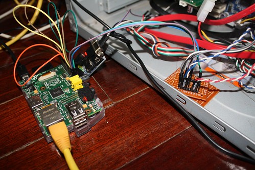
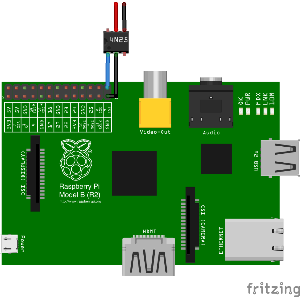
I soldered 2 optocouplers that I have (4N25) to a small perfboard with a pin header. Then I use solderless breadboard cables to connect the board to Raspberry Pi, and to the PC power and reset button (so I can manually turn on/off using the power/reset button on the PC).

4n25

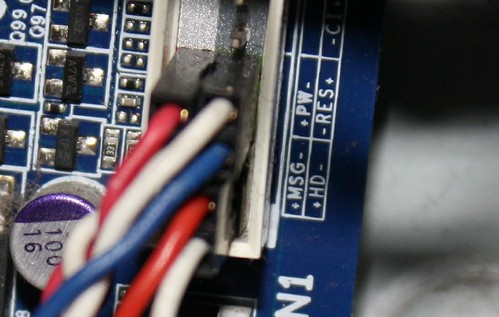
Watch carefully about the + and – on the motherboard (PW is for power, and RES is for reset, note the polarity is important for the optocoupler, on the picture above: Red goes to + and Black goes to -):

I could just have used one optocoupler to connect to the power button (the reset is not really necessary, because we can turn off and on the PC again to reset), but I just want to use the extra 4N25 that I have (it’s really cheap, 5.5 baht or around 17 cents USD).

To reset the PC, I just set the GPIO pin to high for about one second, then set it low again. To power up the PC, I set the GPIO pin to high for about 5 seconds, and set it low again (the same can be used to forcefully power down the PC).

Resetting and powering the PC is easy, the next task is to know what happened if the PC crashed. To do this, I need a serial connection. If my PC has a serial port and I have a USB to serial cable, then everything will be much easier, but since I don’t have a USB to serial cable, and my PC doesn’t have a serial port on the back, it gets a bit complicated.

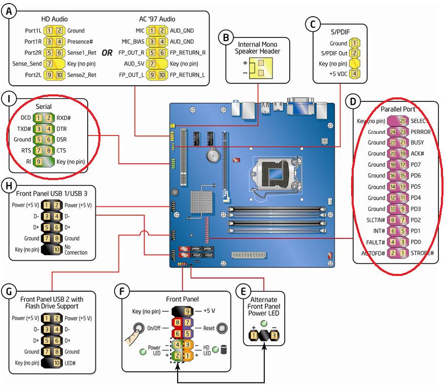
I still have a small board based on MAX3232CPE to convert from 3.3V serial to 5.0 V, so I plugged that board to Raspberry Pi and connected it directly to the PC motherboard. This page helped me in finding the pin names (I only need to connect RX, TX and GND).

mb

On the Raspberry side, I need to set up so that it will not use the serial port for kernel output and log in. You can follow the guide here.

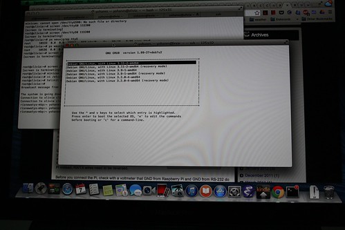
On the PC side, I need to activate serial output in three places: to accept login (getty), to get the kernel output (kernel parameters in grub), and in grub itself (to show the boot selection dialog). This guide for Debian works for me, but I was not able to see the GRUB output on screen when I connected my screen (I can only see the output on my serial console, but this was not a problem for me).

I experimented a little bit with SGABios Hoping that I would be able to see BIOS output from my serial port. It didn’t work as expected. I can not see the initial BIOS screen, and I can not send a key to enter BIOS setting, but If I connect a keyboard and press a button to enter the BIOS, I can see the BIOS menu via serial port and I can interact with it.

Here are the steps that I tried to get the BIOS serial output: I downloaded the BIOS for my motherboard (an AWARD BIOS). Then on a windows machine, I modified the BIOS using CBROM cbrom bios.bin /isa sgabios.bin. Then I flashed the BIOS from Linux using Flashrom.

I didn’t solve the BIOS problem due to time constraint. There are several solutions that I can think of to solve this: one is to use CoreBoot (but unfortunately my motherboard is not supported by coreboot), another one is to try to do more hacking on the BIOS (maybe removing the VGA ROM to force the output to serial port) and the other one is to simulate a keypress to enter BIOS. The first two methods may not be portable across BIOS, but the last one should be portable. The key simulation can be done by simulating a PS2 device (using bitbanging on Raspberry Pi), or USB HID device. A super simple USB HID device can be made by using V-USB library (you can see this as an example).

Just a few hours before I left, I have an idea to connect a temperature sensor just to see if the temperature around the PC case is too high. We are entering the summer here in Chiang Mai and the outside temperature is getting higher every day (from November to beginning of February, the temperature was around 8-20 Celcius, and now it is around 17-37 Celcius). It was quite easy to add the temperature sensor, I just use the guide and driver from adafruit. Next time I may add an infrared LED on the Raspberry Pi to turn on the Air Conditioner when it gets really hot.

Having everything setup: nothing happened while I was away. The PC was running nicely (and I can access the PC via SSH and the serial console).

RFID based toy/game for toddlers

Hardware

Inspired by this toy fromm LeapFrog that we got for free on a yard sale, I made this toy for my son:

IMG_00000866

This is a simple toy, he can pick a card from this set of alphabet cards:

IMG_00000853

And put it above this device:

IMG_00000854

And then the alphabet will be shown on the screen:

IMG_00000861

the alphabet is received by Raspberry Pi via bluetooth and displayed through HDMI:

IMG_00000863

Why wireless? I want to have distance between the device and the TV screen. I could have just used cables (I can even plug the RFID reader directly to Raspberry Pi), but it is not toddler-safe. My son would occasionally run to the TV screen to point at something, and I don’t want him to trip on the wires.

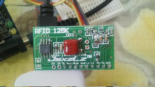
The implementation is quite simple. The cards are actually RFID cards (50 cards for $11.47), and it is read using this cheap 9.9 USD RFID reader. To make the card looks good, my wife prints the letters of the alphabet to a sticker paper and sticks them to the cards.

IMG_00000887

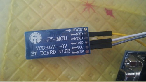
And to make the data available to the Raspberry Pi, I used the same Bluetooth module as the one I used in my previous post (you can find a similar one here). The baud rate for the RFID reader is 9600 bps, so we need to set the same baud rate for the Bluetooth module.

IMG_00000884

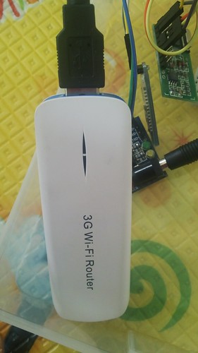
For the power source, I could have used AA batteries, but I have this USB powerbank (that also acts as a USB/Wifi router) that I don’t use very often:

IMG_00000876

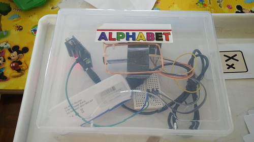
I didn’t do any soldering for this project, I used a breadboard

IMG_00000882

And in case you are wondering, I just use this device (5v to 3.3v serial converter) to connect the USB power to breadboard (just because I don’t want to solder anything, and this device fits nicely):

IMG_00000875

Software

For the software part, I wrote a small python script that uses pygame.

To prepare the raspberry pi to run the app, you need to install these packages:


sudo apt-get install python-pygame python-serial bluez-utils sox

Then find the device bluetooth address using:


hcitool scan

Create a file named “pincodes” to enable automatic pairing:


echo "DEVICEADDRESS PIN" >> /var/lib/bluetooth/YOURMACHINEADDRESS/pincodes

The default device PIN is 1234. For example, this is what I do in my laptop:


echo "00:12:03:09:17:55 1234 >> /var/lib/bluetooth/E0\:B9\:A5\:45\:15\:1B/pincodes

And for the serial connection, create /etc/bluetooth/rfcomm.conf file:

#
# RFCOMM configuration file.
#

rfcomm0 {
	# Automatically bind the device at startup
	bind yes;

	# Bluetooth address of the device
	device DEVICEADDRESS;

	# RFCOMM channel for the connection
	channel	1;
}

You can checkout the source code at github:


git clone git://github.com/yohanes/rfid-abc.git

I don’t have a license to redistribute the wav files for the alphabet sound that I own, but fortunately you can find a collection of wav files from Voxeo site: http://evolution.voxeo.com/library/audio/prompts/alphabet/index.jsp (download audio-alphabet.zip)

To be usable in pygame, you need to convert the format to raw 44.1Khz WAV using sox:

cd rfid-abc
wget -c http://evolution.voxeo.com/library/audio/prompts/alphabet/audio-alphabet.zip
unzip audio-alphabet.zip -d original
cd original
for i in *.wav; do sox $i -r 44100 -e un ../$i; done
cd ..

And to run it:


python game.py

Oh wait, you need to edit the card id mapping in map.txt, in case you didn’t touch the file the app will store unknown card ids to “unknown.txt”.

Future improvements

The software is still very simple. I am planning to make it multilingual (my son needs to know Indonesian, English and Thai), and more interesting (for example: the computer can ask “find me the letter C” or it can be changed into a spelling game).