TLDR: If your FL2K dongle only works on USB 2.0 ports, it may have been wired incorrectly. Rewiring it should make it work.
Two weeks ago I learned about osmo-fl2k from Hackaday and immediately ordered one from Aliexpress. Two days ago, I received my order and tested it: it works with USB 2.0 ports on all of my computers (Windows and Linux, Desktop and Laptop), but when I plugged it in on a USB 3.0 port, it is not detected at all.
I verified that the device ID is as expected by osmo-fl2k and that it works (with fl2k-test) on USB 2.0 port although it is very slow (14 MS/s).
The device is never detected on USB 3.0 ports, with or without hubs. No message at all when typing “dmesg”, and Windows also doesn’t show anything on device manager (not even a blink on device manager when the device is plugged in). I verified that all of my USB 3.0 port works by plugging other USB 2.0 and USB 3.0 devices.
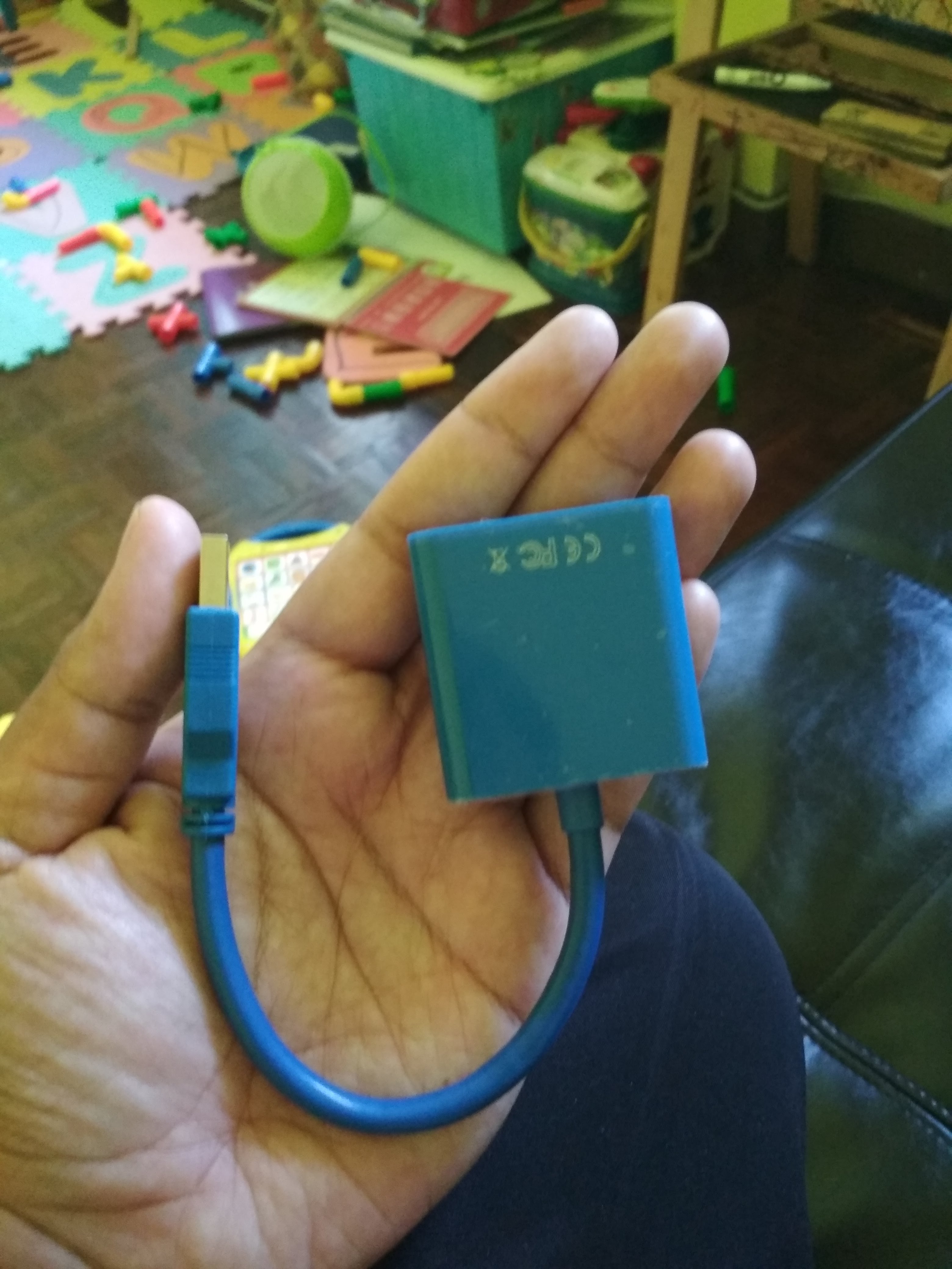
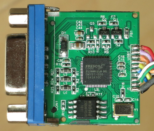
Next step is to open this thing to verify that I really get the correct chip. Fortunately, the chip is correct, although the PCB is a bit different from the one shown in the osmo-fl2k website. The cable soldering seems to be ok, the connection looks good, and they even hot-glue it to make sure it stays that way.
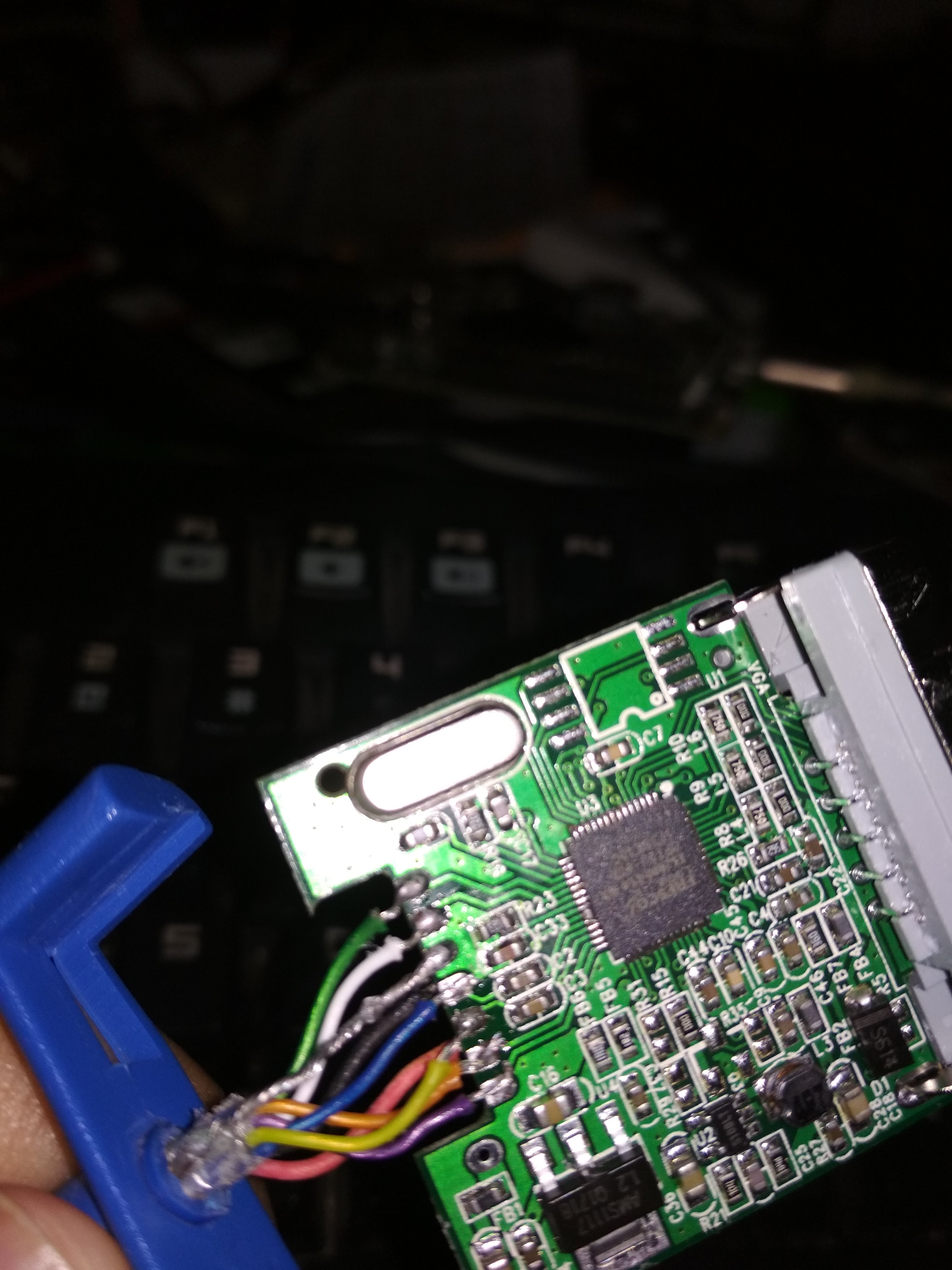
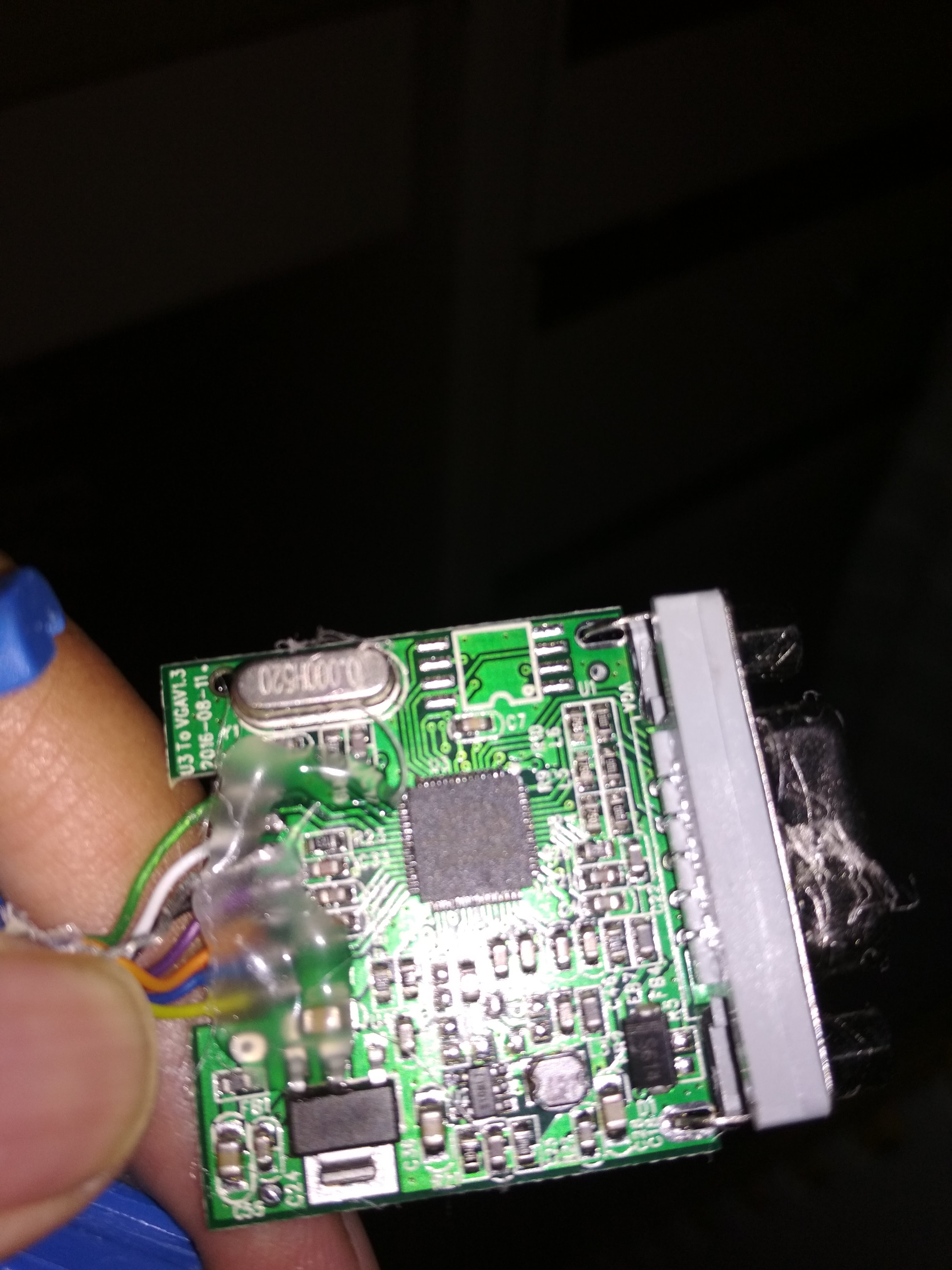 I began to notice that the cabling is a bit different from the one shown in osmo-fl2k website. On the website all 10 cables is on the front side of the PCB, and on mine there are only 8 of them on one side and two on the other side.
I began to suspect something is wrong with the SSTX+/SSTX-/SSRX+/SSRX- cabling. But there is no specification/datasheet for the Chip, so how can I know the correct cabling?
First I tried using my multimeter’s continuity tester to check the color of the cables and the connection. It matches the standard coloring as listed in the USB 3.0 page on Wikipedia. For example, testing D+ pin on the USB port shows that it connects to the green cable and D- connects to the white cable.
I made an assumption: the quality of dongle used on the FL2K website looks good (mine doesn’t even have the SPI flash chip), so I assume they also use standard colors for the cables. Tracing from the pins to the cable shows that I need to rearrange the cables to match. For example, the first two pins on the top right of the chip should go to purple and orange cables (SuperSpeed receiver differential pair).
After rewiring it, it works fine, the dongle is detected on USB 3.0 ports and I can transmit up to 108MS/s. I have an old motherboard (>5 years), and as you can see from the osmo-fl2k website that the transmission speed depends on the USB 3.0 controller that you have. I have successfully transmitted FM radio signal but I haven’t experimented with other types of signal yet.
So the explanation of why it works on USB 2.0 ports is because it only uses VCC, GND, D+, and D- which was wired correctly. While on USB 3.0 ports, it tried to use the SSTX/SSRX pair and it doesn’t work.
I hope this helps others that have the same problem. Just a word of caution: the colors of your cables might be different from the one that I have, the PCB layout that you receive may also be different, so be careful and double check everything.
The cheaper no-brand dongles around $5 give various problems like the one shown here, it is preferable to spend $ 15 and buy the Maiwo FL2K dongle version.
https://hackernoon.com/osmo-fl2k-a-15-dtv-transmitter-fm-radio-hijack-and-gps-spoofing-device-68ac08ba7d76
Note that cheap dongles also get the USB cable coloring wrong. Mine was all sorts of wrong…
Many thanks for posting it.
I’m waiting a unit from AliExpress and I imagine it will be similar to your one. It seems from picture that the PCB is 2 layers. It will help to draw the shematics.
Have you found some other info of the FL2000 ?
I have not found any new info. But I think I will try to draw the schematics for the USB cable if it can help others.
Well done. I think i have the same problem. How did you know what belongs where? On your photo nothing is labeled. On mine there are labels but only for D+ and D+ the rest are just numbers. I checked with https://en.wikipedia.org/wiki/USB_3.0 but the numbers don’t match. Can any1 tell me where to look for that?
First: check if the cable colors match the connectors (Wikipedia has images for every connector types). This is done by multimeter to check If it matches the picture (e.g: the D+ in the USB head should be green). If the color matches, then its good, if not, then you need to list the correct mapping.
The next step is to match your PCB with the one from the FL2K site, it should be in that order.
Can Osmo do WSPR. It would seem like the ideal use case?
Thanks for posting this, I have an almost exact dongle as yours but I haven’t been able to successfully transmit FM radio signal (I think the USB3.0 is working as Debian in VMware detects it when I try to run fl2k_fm), I tried changing it to 87.5 MHz by changing the carrier and sample rate but my FM radio receiver didn’t seem to get the signal. Did you use a regular FM radio receiver for the tests? How can I know if it is working or not without a RF Spectrum Analyzer?
I am using standard radio receiver: put a small wire as an antenna for the for the dongle, and put the radio antenna very close to the dongle antenna.
Thanks, I’m going to try this!
Thanks, it worked!
Hello,
My PCBs are different, and I can not run the software with the parameters on osmocom Wiki for fl2k.
http://zupimages.net/viewer.php?id=18/42/o9nu.jpg
http://zupimages.net/viewer.php?id=18/42/b7qm.jpg
With both the only parameter of sample rate that allows me to have a result is 10e6 up to 14e6 than it be on USB2 or USB3. I conclude that my problem is probably the one exposed here (bad wiring), only at the sight of my photos we can see that I do not have 7 connectors like you but 9 on mine so I do not know how well to rewire them .
I think the red wire first is the VCC (+5v) because it works in USB2/USB3 as well as the SR is low to run the software, and on the other side there are two possible connections (GND1 and GND2 : 2 mass and “-“).
The two are wired differently which makes me say that they are not suitably neither one nor the other.
How to determine the right wiring?
Black is wired as follows: Red, Yellow, Blue, Orange, Purple, Black, White, Green.
Blue when it is: Red, Blue, Yellow, Purple, Orange, Black, White, Green.
Seeing that it works in USB2 with a Sample Rate of 14e6 I think the USB2 part (Red, Black, White, Green) is well cable.
Would you have a schema as you propose to transmit Admin?
Thank you in advance for your help and your help.
Hello, my PCBs are very different, and I can not run the software with the parameters on osmo-fl2k wiki.
http://zupimages.net/viewer.php?id=18/42/o9nu.jpg
http://zupimages.net/viewer.php?id=18/42/b7qm.jpg
With both the only parameter of sample rate that allows me to have a result is 10e6 up to 14e6 than it be on USB2 or USB3. I conclude that my problem is probably the one exposed here (bad wiring), only at the sight of my photos we can see that I do not have 7 connectors like you but 9 on mine so I do not know how well to rewire them .
I think the red wire first is the VCC (+ 5v) because it works in USB2 / USB3 as well as the SR is low to run the software, and on the other side there are two possible connections (GND1 and GND2: 2 mass and “-“).
The two are wired differently which makes me say that they are not suitably neither one nor the other.
How to determine the right wiring?
Black is wired as follows: Red, Yellow, Blue, Orange, Purple, Black, White, Green.
Blue when it is: Red, Blue, Yellow, Purple, Orange, Black, White, Green.
Seeing that it works in USB2 with a Sample Rate of 14e6 I think the USB2 part (Red, Black, White, Green) is well cable.
Would you have a schema as you propose to transmit Admin?
Thank you in advance for your help and your help.
Mine got fixed with one of the sequences you posted:
Red, Blue, Yellow, Purple, Orange, Black, White, Green
Mis-wiring as it came from China was gross. Even ground was connected to one of the signal pads.
When I buzzed it from USB3 connector to the board it became clear that high speed wires do not follow standard convention on the USB connector side, and yours can be messed up in a different way. Map colors to connector pins using wiki for USB3 A male connector and then follow the sequence for the reference board published on osmocom site assuming that colors are correct on that one, i.e.
VBUS SSRX- SSRX+ GND SSTX+ SSTX- GND D- D+ GND
qty of ground pads may vary
Help me please.